You might remember I played around with Kicad a few months ago and made this tacky little thing. Just about 2 1/2 weeks ago I went onto DirtyPCB to get them actually made. I wanted to have gone through the production process and get something built before I started doing more complicated projects.
Unfortunately I discovered a little mistake with the design in the layout that ended up at the manufacturer (Rev 3.1). I tried to fix them but Rev 3.2 didn't make it in time, which means my boards will be a bit more complicated to power. However not too complicated as the power-in are just throughholes so I can actually strap anything behind it to power it.
But without further a due, here is the result from DirtyPCB (which I am actually quite impressed with).
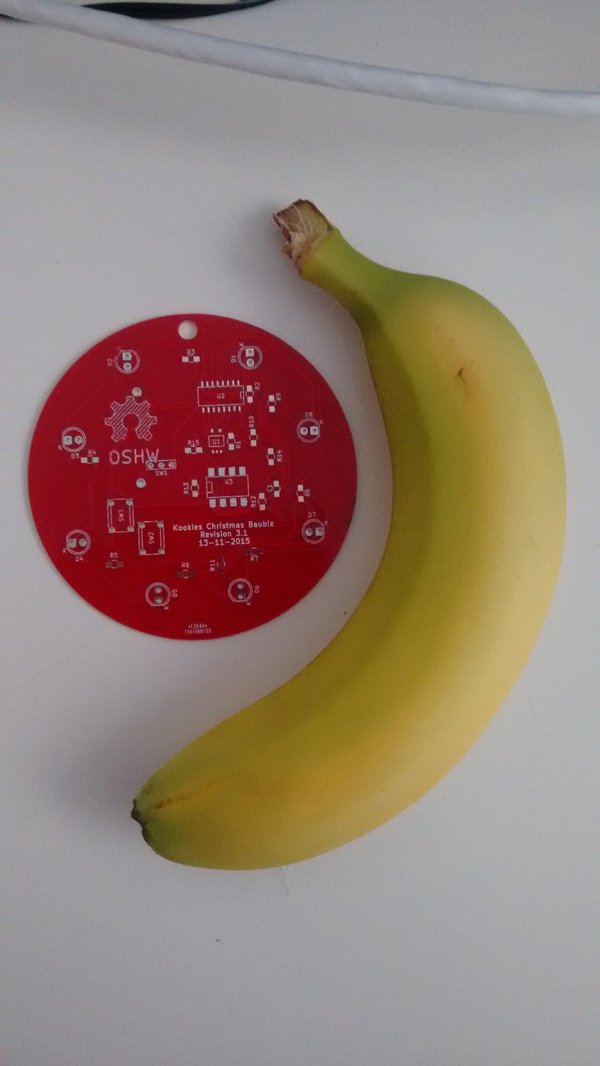
Now, I'm new to all of this so I started doing beep-tests on the pads to make sure things were properly connected and all the boards passed them. The production quality is pretty good. Unfortunately I can't start assembling them yet just because none of the parts I ordered for them have arrived yet. The manufacture and shipping of the boards actually beat the shipping of off-the-shelf parts!
Anyways, I'm kinda excited. First time making an electronics project. I might post another update on when the parts arive and post a few gifs of the finished products. If I don't I'll probably tweet about it though.
Now, I have another smaller electronics project in the making where I am, again, waiting for parts to arrive to do some testing. And already designing a modular PCB board. (Limited a bit with the 10x10cm limitations on DirtyPCB I need to design my project in a way that I can take a bunch of smaller panels and stick them together into a large one, which would take hundreds of dollars to make elsewhere).
😊
Anyways, enough ramblings. Read you later.
Update...update
Right...so after tinkering with the bauble a bit I found out a few things. The most important one being that I made some mistakes. Some big ones :)
- Pin 9 of the shift register was connected to both input A and input B of the XOR gate. Which meant that both inputs were always the same...which also meant that the output was always 0.
- The 555-timer clock ran at several hundred kilohertz. I had to change the capacitor down to ~12µF and the resistors to ~4.7 ohms.
- The coin-cell battery didn't have enough juice to run it. Two had to be put in parallel. Even then, two batteries would not be able to run for very long.
To make the bauble work I bridget the xor gate completely, so just feeding back the shift register end to the beginning.
In addition to those things some of the LED's sometimes didn't work. I'm not sure if that is due to broken shift registers, traces or LEDs. All in all I do consider it to have tought me quite a lot about electronics, going through the process of producing a PCB and debugging electronics once it arrived and inevidably goes wrong :)
I am currently in the process of redesigning the entire circuite from scratch. And making it easier to solder. I want to make it into a beginner soldering kit that people can both learn how to solder with and also have something to hang off their christmas tree in the jolly season.